 San Antonio Area Hams


 In
March 2004, Bob took a trip to a clear area in Shertz Texas to setup
his new IK-STIC 2 antenna mount. It was made by shortening a child's
small metal bedframe for the stand and adding a PVC mast (painted green)
so all he has to do is screw in a PVC-to-metal shaft and slide the antenna
on it. The model shown here is the newer version of his IK-STIC2 and
with a tuner covers 160-10 meters. It stands only about a foot taller
than the standard version (without the mount, 5 ft with the mount making
the total height 30 ft ), but has a longer bottom coil with many more
turns. The adaptation procedure was posted at the end of the IK-STIC
2 web page in February 2004.
In
March 2004, Bob took a trip to a clear area in Shertz Texas to setup
his new IK-STIC 2 antenna mount. It was made by shortening a child's
small metal bedframe for the stand and adding a PVC mast (painted green)
so all he has to do is screw in a PVC-to-metal shaft and slide the antenna
on it. The model shown here is the newer version of his IK-STIC2 and
with a tuner covers 160-10 meters. It stands only about a foot taller
than the standard version (without the mount, 5 ft with the mount making
the total height 30 ft ), but has a longer bottom coil with many more
turns. The adaptation procedure was posted at the end of the IK-STIC
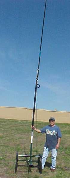
2 web page in February 2004. 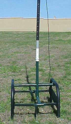 At the right you see a photo of W2IK holding his antenna following his
quick 5 minute installation process. The antenna is fed at the point
above the coil you see several feet above where Bob is holding on. Bob
recommends using nylon rope as guywires if you are expecting heavier
than moderate winds, but this mount works great in an area where you
can't normally run guy wires for some reason. Total height is about
30 feet above the ground.
At the right you see a photo of W2IK holding his antenna following his
quick 5 minute installation process. The antenna is fed at the point
above the coil you see several feet above where Bob is holding on. Bob
recommends using nylon rope as guywires if you are expecting heavier
than moderate winds, but this mount works great in an area where you
can't normally run guy wires for some reason. Total height is about
30 feet above the ground.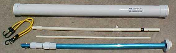 The featured photo above shows the W2IK emergency deployable 2 meter J-Pole antenna that also works on 440 quite well. When slipped inside the tube (that also serves as the base) the total size is less than 48" long. Easily shipped with a weight less than 5 pounds (excluding weight of coax). We'll be posting links here to let you build your own antenna for about $30 using parts from your local hardware store (excluding the radio coax connector and coax that you can't get there).
Tip #2 - HF Antenna - NVIS type - 2006 Design
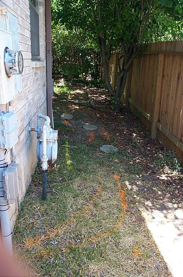
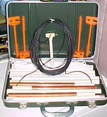 As shown in the picture to the left, I made a few minor changes to the original design of this NVIS antenna kit. I replaced the hammer-in support rope stakes with a screw-in variety. At first I thought that they wouldn't be able to withstand the torque or pullout stress. A few tests showed me I was wrong. They are easy to use and easier to remove from either soft or hard soil while still supplying enough strength so that they won't pull out like a conventional stake might.
The picture also shows the kit without the coax cable and ground reflector system that were a part of my other pictures. I did this to give you a better view of the antenna, itself. The ground reflector system is very important in creating the RF waveform needed for NVIS signals and I have designed a reflector system which is easy to deploy yet suits the ground conductivity of our area. It took many field strength experiments to come up with the ideal reflector design.
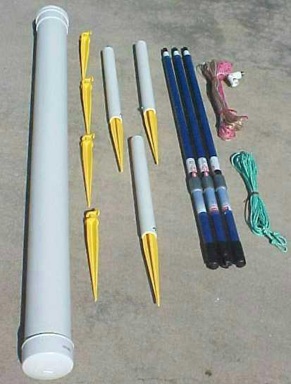
There are three antenna supports, all of which are 5 feet tall when assembled. This height, after field testing, I feel is not only RF adequate to create the "half grapefruit" lobe needed for communications within a 400 mile circular range but it also makes the antenna easier to handle and construct. With this height above ground, it also means that it lessens the reception of both static crashes AND European broadcasters on 40 meters making it very valuable during emergency communications in south Texas. If every emergency communications operation in south Texas, that used HF, were wise enough to also use the same type of antenna system it would make a very reliable communications web between all counties. I have also designed a NVIS antenna system which will create the same radiation pattern when it is installed on the roof of a building, such as at an emergency operations center. The reflector system is completely different to compensate for "pooling" and nearby metal structures.
Visit http://hometown.aol.com/alonestaryank/NVISKIT.html for more details, construction instructions and full parts list for building your own portable Texas NVIS Antenna. 73 de Bob W2IK
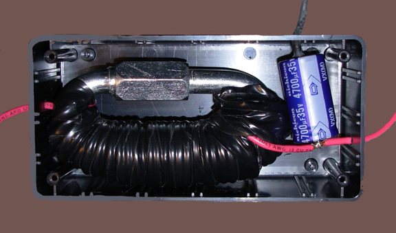
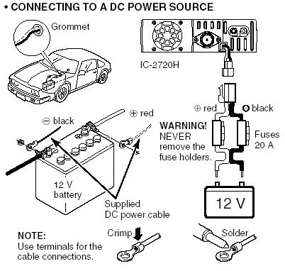 Power
source
Power
source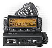
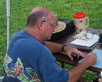
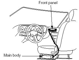 When
you install your mobile rig in your vehicle, be aware that they don't
like heat, so keep them out of direct sunlight when possible. Also,
the rule of "out of sight, out of mind" applies very well
to avoid attracting attention of those interested in "collecting"
radios from "involuntary donors". Keep the radio mounted where
you can easily see the display while driving.
When
you install your mobile rig in your vehicle, be aware that they don't
like heat, so keep them out of direct sunlight when possible. Also,
the rule of "out of sight, out of mind" applies very well
to avoid attracting attention of those interested in "collecting"
radios from "involuntary donors". Keep the radio mounted where
you can easily see the display while driving. 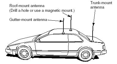 There is an old saying "You aren't a real ham until you've drilled a hole in the roof
of your truck for an antenna to mount." Not sure everybody buys
into that saying, but there is a definite advantage to each method
of mounting.
There is an old saying "You aren't a real ham until you've drilled a hole in the roof
of your truck for an antenna to mount." Not sure everybody buys
into that saying, but there is a definite advantage to each method
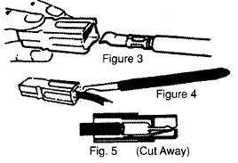
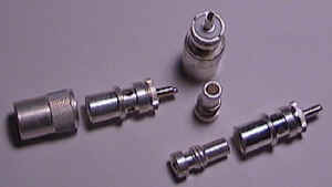
of mounting. 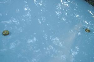 (No,
it wasn't after the hail storm!) They professionally drilled two holes
in his roof, installed quality NMO style mounts (sometimes referred
to as "Motorola style"), ran the coax under the roof liner,
down the passenger side front column between the front windshield
and the front door, down into the front carpet area of the van. They
installed connectors on both coaxes, labeled them appropriately, ran
the new power line from the battery through the firewall to the same
area, all for a little more than $100. The ham later routed the coax
himself under the door jamb and behind the passenger seat in a secure
manner that reduced the chance of accidental snagging.
(No,
it wasn't after the hail storm!) They professionally drilled two holes
in his roof, installed quality NMO style mounts (sometimes referred
to as "Motorola style"), ran the coax under the roof liner,
down the passenger side front column between the front windshield
and the front door, down into the front carpet area of the van. They
installed connectors on both coaxes, labeled them appropriately, ran
the new power line from the battery through the firewall to the same
area, all for a little more than $100. The ham later routed the coax
himself under the door jamb and behind the passenger seat in a secure
manner that reduced the chance of accidental snagging.