 San Antonio Area Hams
For many years I was very reluctant to install PL-259 coax plugs. It seemed as if it took a very long time to install one, and then there was a good chance that I would short out the plug, or that it would have an undetected cold-solder joint that would lead to problems, over time, outside. Since my HF antenna was often a multiband dipole fed with open-wire line, the only coax I needed was a short jumper between the radio and the tuner, and this was easily available from many sources.
Finally, the day came when I became very interested in antennas, and endless experimentation led to the need for many different lengths of coax, in many different types. It was time to figure out how to (successfully) install PL-259 plugs.
Like so many things in life, the secret turned out to be using the right tools, and developing some experience by simply installing plugs. Over a short amount of time, I developed confidence in my technique, and now I trust my work far more than commercial work. In fact one of my more recent repair jobs was replacing the coax plug on a commercial mobile magnetic mount that became intermittent after less than a year of use.
This page contains my tools, technique, and tips.
There are many sources of information on how to select and install coax plugs. The ARRL Handbook and ARRL Antenna Book are always good sources of information. Several commercial sites provide information as well as actual connector parts. Two of my favorites are the Radioware and Radio Bookstore and The Wireman, Inc.. These sources, and many others, provide information on selecting connectors (and coax), as well as installing them.
For those of you who are fans of the Three Stooges, you will remember that the answer to the question, What Tools?, is, the tools we have been using for the last 20 years. Well, I have not been using these tools for 20 years, but they are the tools that I use. [Please click on a picture for a larger view.]
The left picture shows the most important tools. The picture includes:
Butane torch and refill cylinder: For me, my most important coax plug soldering tool is the butane torch. I use what is called a hand torch. It runs off of butane, and can be refilled from the same cylinders used to recharge cigarette lighters.
Coax Strippers: A coax stripper makes the job of prepping the cable end fast and accurate.
Vise Grips: The two vise grips I use provide mechanical support during the soldering process as well as a heat sink to conduct away excess heat.
Diagonal Pliers: Even with a well-adjusted coax stripper, it helps to have a good diagonal pliers to trim and dress the braid, center insulation, and center conductor. By good, I mean sharp. Ideally, you have two pairs. A larger pair for cutting through the entire cable, and a smaller pair for trimming and fine adjustment. Another good tool for this application is a specific wire cutter/stripper that has an adjustable stop. I often use this tool to cut the center insulator when I'm using a two blade stripper.
Volt-Ohm Meter: The Ohm meter is used at every step in the process to make sure that the coax is not shorted by some mistake in the process. At the end, the overall cable can also be checked for continuity between the ends. [NOTE: if you are adding a connector to a cable where the other end of the cable is permanently attached to an antenna, simple DC resistance checks may not be appropriate. This would be true, for example, if your antenna presents a DC (but NOT RF!) short to ground. In this case, it is more complex to be sure that the connector you are adding does not have a short across it, and has continuity with the antenna. If you wish to check your work, you will need to use an antenna analyzer, or similar device that allows a more complete (beyond DC resistance) measurement of the system.]
Many people use soldering guns as a heat source. In order to have enough heat, the gun should have a high wattage rating, perhaps over 200 watts. Personally, I much prefer the butane torch. I find that the guns really don't have enough heat, they take too long to heat up and too long to cool down, and, the cord always seems to get in the way. The torch has plenty of (instant) heat, the flame is very focused, the torch is lightweight, and it is highly portable. I have installed connectors in the middle of winter, outside, in temperatures under freezing. So long as there is not too much wind, the torch will do the job. I can't see myself ever going back to a soldering gun, but many people do get good results.
To use the hand torch, you simply open the gas value, press the igniter once or twice, and you then have a flame, ready to go. The barrel of the torch has an adjustable air mixture opening for fine-tuning the flame.
Although I have purchased several of the hand torches from different brands, they all appear to be the same basic unit. They may have a different color body, but that's about the only difference I could find. I have paid as little as $9 (USD, 1998 timeframe) and as much as $30. These torches are usually available at hardware stores, or other tool-specialty shops.
I use garden-variety solder made for electronics, not plumbing or jewelry. The solder is the 60/40 type, with a rosin-core to provide flux (not acid-core). There are a few solder products on the market that advertise the ability to solder with less heat at lower temperatures. I have never used these products, but they look interesting. I have seen demonstrations where they are used for exactly this application, and they seem to do a good job.
Soldering is best done on clean, untarnished, surfaces. If your connectors show any sign of tarnish or discoloration, you may want to shine them up with steel wool. If you do that, however, be sure to remove all metal residue, so that the little bits of metal cannot form a short circuit. Compressed air will probably do the job. Another situation where tarnish and corrosion can occur is when you are adding a connector to the end of a cable that was cut (accidentally, no doubt) and then spent some time outside. Water and moisture can penetrate inches to feet inside of the exposed end of a coaxial cable. You have little choice other then to keep cutting the cable shorter until you reach clean and uncontaminated braid and center conductor.
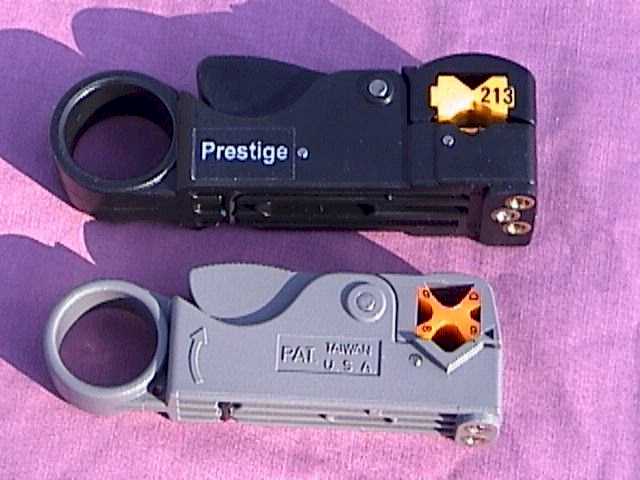
I have found that it is nearly essential to use a coax stripper to prepare the end of the cable. Two of the ones I use are shown in the above right picture. The coax stripper has spring-loaded jaws that hold one or more blades against the cable. The tool is rotated several times around the cable, and the blades all penetrate to their set depth. You can then remove the cut pieces. Ideally, you are ready to go.
In practice, however, it is usually never quite this easy. Some manual trimming may be necessary. Between misadjustment of the stripper, gradual dulling of the blades, and variations in the exact dimensions of the cable, some part of at least one cut will be imperfect. But, it still beats trying to prepare an end by any other method.
All of the strippers feature a rotatable plastic cam which is used to adapt the stripper to different sizes of cable. The cams appear in the above picture. One is yellow, and the other is orange. As you remove, rotate, and replace the cam in the stripper, the spacing between the blades and the cam changes, adapting to different diameter cable. While this works in theory, I have found that it is easier to own several strippers and keep each adjusted to a particular cable configuration.
Strippers come in either two blade or three blade versions. A two blade stripper cuts the outer jacket and the braid. A three blade stripper also cuts the center insulation (around the center conductor). Each blade on the stripper is adjustable via a set screw on the bottom of the stripper. The screw pushes the blade further into the cable. The set screws can be seen in the stripper photo. When you get your stripper, you should adjust it for use. Simply keep preparing ends until you get the desired result. This process can take some time (and some coax!).
Two blade strippers can be purchased for approximately $12 (USD, 1998 timeframe). The two blade unit in the picture came from Radio Shack. Three blade strippers are a little harder to find, and cost a little more money, approximately $30. While a properly adjusted three blade stripper is just a pleasure to use, I find that I use a two blade unit for most of my work.
No matter how you prepare your cable for the connector, the age-old advice is to never nick the center conductor. So, it is better to adjust your blades to be slightly less aggressive than to cut into the center conductor, or into the center insulator for that matter (when cutting through the braid).
Back when I was pretty darn ignorant about coax and connectors, I thought in terms of two cable sizes - what I called thick and thin. The thick cable seemed to be about 1/2 inch in diameter, and carried lots of power. It was represented by products such as RG-8. The thin cable seemed to be about half of the diameter of the thick cable, carried far less power, and was represented by names such as RG-58 and RG-59. As they say, this is close, but no cigar. Here's a slightly more accurate view that will go a long way.
While there are many coax cables that are 1/2 inch in outside diameter, the true size of the cables that interface directly to PL-259 plugs is 0.405 inches. If you have a cable which is more than 0.405 inches in diameter, you can be pretty sure of a few things. First, it is probably a good quality/low loss cable. As a very general rule, subject to many factors, a larger cable has less loss (and usually a higher power rating). Second, you may have a difficult and/or expensive time getting connectors for the ends. While there are some very interesting techniques to adapt larger cables to PL-259 plugs, this page will not consider them. That's a whole world unto itself.
The standard PL-259 (also known as a UHF connector) is designed to directly accept 0.405 inch diameter cable. This includes popular cables such as RG-8, RG-213, and RG-11. While there are differences between different types and brands of PL-259 plugs, all will accept the 0.405 inch cable.
The so-called thin cables are a bit more complex to categorize. Most of the common cables fall into one of two diameters - either 0.195 or 0.24 inches. RG-58, for example has a diameter of 0.195 inches. RG-59 and RG-8X have a diameter of 0.24 inches.
There is only one PL-259 plug (in terms of size), regardless of the diameter of the cable. The thinner cables are installed with the aid of an adapter. The adapter screws into the PL-259 and provides a diameter reduction to the smaller size.
I know of two popular adapters, one for the 0.195 inch and the other for the 0.24 inch diameter cables. Perhaps there are more, since there are other thin cable diameters out there. But, for the vast majority of common thin cables, these two adapters will do the job. The adapter for the 0.195 inch cable is also known as the UG-175. The adapter for the 0.24 inch cable is the UG-176.
At the end of the day, for most amateur radio purposes, the parts needed for installing coax connectors include the PL-259 itself, and the UG-175 or UG-176 adapter, if you are going to be working with a thinner (0.195 or 0.24 inch) cable.
This page is really about installing PL-259's, not the connectors themselves. The catalog from The Wireman, Inc, called The Wirebook, contains a large amount of information about the different types of PL-259 plugs. The cost of a plug will depend upon the quality of the plug and the quantity purchased. Good quality plugs, purchased in quantity (10+), can cost around $1 (USD, 1998 timeframe) each at places such as hamfests. Purchased one at a time, from a specialty store, the cost might be as high as $4 per connector. I try to find quality plugs at hamfests and buy them in bulk. Usually, these are the silver-plated plugs with a Teflon center pin insulator. I have also ordered plugs and adapters over the Internet, and there are many good outlets.
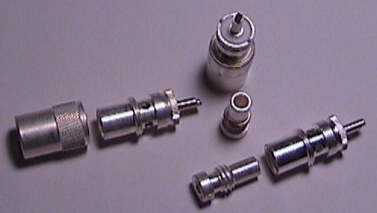 |
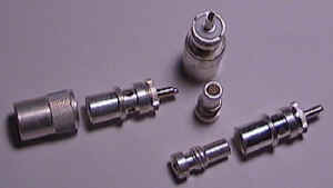
One last point. I mentioned a few paragraphs back that all PL-259 connectors are the same size. This really isn't true, there will be some variations between brands and even from plug to plug from the same brand. I have not found that those small variations make a difference - with one exception. One of cables I have used is RF-9914F, BuryFlex (TM). This is a low-loss cable which can be directly buried in the ground, and bends into tight loops because the center conductor is stranded, not solid. It is a rugged cable available from the Radioware and Radio Bookstore. Its stranded center conductor is just ever so slightly larger than most all center pin holes. I find that approximately only one out of five different brands of PL-259 plugs will accept the conductor. With this exception, plugs may differ in quality, but they are otherwise interchangeable (in my experience). |
| PL-259 Plug and Adapter Examples |
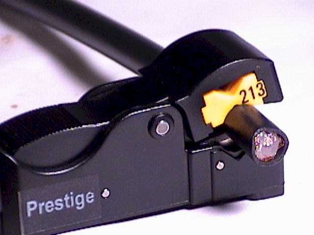
The process begins by cutting the cable to expose an end. The stripper is placed over the cable, with about an inch of cable between the stripper and the end. See the left picture below. You must put the stripper on the coax in the correct direction. That is, the blade settings determine which side of the stripper is nearest to the end. Be sure that this side is towards the cut end of the cable. Now comes a very important point. When rotating the stripper around the cable, be sure to rotate it in a clockwise direction, when looking at the cable from the exposed end. This is important for several reasons. First, this direction causes the blades to cut from back to front. This tends to keep the cable within the stripper. If you rotate in the other direction, there is a greater tendency for the cable to want to walk out of the stripper jaws. This is especially true as the blades become more and more dull, and cut with more and more friction. The second reason is that this clockwise direction is the same direction that will be used to install the PL-259 when it is screwed onto the end of the cable.
In the ideal world, the braid would be cut cleanly without being moved. The truth is, however, that the act of running the stripper around the cable causes the braid to twist around the center insulator as well as be cut. You want this twist to be in the same direction as the PL-259 threads. If you run the stripper in the other direction, the braid will want to untwist when you are screwing on the PL-259, and this just makes an unnecessary problem. If you look closely at the middle picture below, you can see how the very end of the braid is twisted to run around the center insulator. This is just an unavoidable side-effect of the process of turning the stripper around the coax. It really is not an issue, unless you go in the wrong direction.
Knowing how many times to rotate the stripper is also an art. It is possible to rotate it too few, or too many times. My own experience is that I turn it so long as I can hear the sound of the braid being cut. Yes, this is a very distinctive sound. It usually takes about 5 to 8 turns. A three blade stripper will take more turns than a two blade stripper. Let's remember what's going on here. A set of blades are pressing against a cable by the force of a spring. As the stripper rotates, the blades start to penetrate into the cable. All of the blades need to cut through the one or more layers of different material types. If you do not turn the stripper enough, you will not make a deep enough cut. If you turn it too many times, you may cut deeper than you want. If you consistently are cutting too deep on all of the blades, then you have to readjust the stripper to lower all of the blades together. I mean lower the blades in the stripper so that they penetrate less into the cable.
 |
 |
 |
| Positioning the Stripper | Stripped and Ready | Gripped and Ready |
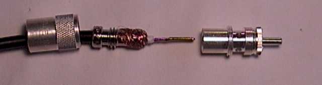
The middle picture shows the end of the cable after being stripped. It took only a few seconds to go from the left picture to the middle picture. The stripper does a great job, very quickly. If you use a stripper to prepare the cable, the blade to blade side spacing, which is not adjustable, will determine the length of each exposed section. As you can see in the middle picture, the length of the center insulator from it's end to the start of the braid is approximately 1/8 of an inch. The exposed braid section is approximately 5/16 of an inch. These dimensions match the typical instructions given in sources such as the ARRL Handbook. The center conductor can be any length, so long as it is longer than the PL-259 center pin barrel.
The middle picture also shows the prepared coax next to a PL-259 plug. The center conductor is more than long enough to extend out of the end of the center pin barrel. The center insulator can seat right against the insulator in the plug. The exposed braid is held back from the end (to discourage electrical shorting), but is yet visible through the holes in the barrel of the plug. Finally, the coax jacket can fully thread into the plug, providing a strong grip on the cable, as well as moisture protection.
The next step is to screw the PL-259 onto the cable. Prior to this step, be sure that all of the fine braid wires are not touching the center conductor. This may sound rather obvious, but some of the braid wires are very fine, almost to the point of hair. All it takes to cause trouble is one stray braid wire, that is not dressed with all of the rest, shorting out to the center conductor. Screwing the PL-259 onto the cable can take some muscle. Usually, the problem is that it's hard to grip the small connector and turn it onto the cable. Here's where I start to employ the vise grips. I use my larger pair to grab the connector and use it as a big level arm to aid in screwing the connector onto the cable. Do not put too much force on the PL-259. They are relatively fragile, and I have no doubt that overly aggressive vise grips could bend them out of round, which would cause no end of trouble. Since the PL-259 and the vise grips are both usually knurled, you can make a firm grip with very little pressure. Show your manliness in other ways.
Oh, by the way - before you screw on the PL-259, please make sure that you first put the outer sleeve onto the cable. I think that everybody has, sooner or later, attached a connector then discovered that the outer sleeve is sitting on the desk. This leads to both a laugh and a tear, and is not a suggested step. Be sure that the outer sleeve is put on in the correct direction. That little variation seems to provide less laughter, and far more tears.
Next, be sure that the PL-259 is completely seated on the cable. As you get closer to this goal, you will see the center insulator then the braid go past the solder holes in the barrel. You should be able to tell that the connector is completely seated by a change in the turning resistance - it should become impossible to screw the connector on any further. Again, this is a step that should be done with moderation. If you tighten the PL-259 too much on the cable you could short out the cable, or, strip the threads formed (cut) in the coax jacket.
The right picture above shows the cable, with a PL-259 screwed onto its end. The outer sleeve is also already on the cable, and even faces the right direction. Here's where I use the pair of vise grips to grab the connector on each side of the solder holes. This arrangement holds the cable in a horizontal position, which is a convenient place for soldering. It also provides a good heat sink in the critical areas of the cable jacket and the center pin insulator. Neither vise grip is too tight. They grab the connector only enough to hold it, not enough to deform it.
Now when I grip the PL-259, I orient it so that two of the four solder holes are facing up. At this point, all we have to do is to solder the center pin, then the four holes in the barrel, and we are done. I do this in two steps. In the first step, I solder the center pin, then the two barrel holes that are facing up. After the end cools down, and I let it cool for several minutes so that I don't risk creating a cold-solder joint, I rotate the cable 180 degrees so that I can solder the last two barrel holes.
Before I solder, however, I use my Ohm meter to verify that the cable is not shorted. If you read a short (0 Ohms), it might not be your connector installation job. It may be true that the opposite end of the cable is providing the short. I have seen cases where the opposite end of the cable has a rough cut - so rough that the braid touches the center conductor. But if you do find a short in your connector, you still can take the end apart and fix it before applying solder. Personally, once I put a plug on the end of the cable, I don't try to fix the end if there is a problem. I just remove the plug, recut the end, and start over with the coax stripper. Another situation which may come up is that the opposite end of the cable is shunted by an inductor. This could happen if the cable directly connects to the base of a mobile antenna, where the inductor is part of an impedance matching network. In that case, the cable will appear shorted for direct current (DC), even though nothing is wrong. Don't falsely blame your connector when the issue is at the other end of the cable. Assuming that the opposite end of the cable is open, the connector end should measure an infinite impedance.
Once I determine that the cable is not shorted, I solder the center pin. I apply the torch flame to the end of the barrel, where I can heat up both the barrel and the center conductor. The usual rule here is to heat the work, not the solder. After perhaps 5 seconds, I can touch the solder to the end of the barrel and it will flow. I try not to get solder on the outside of the barrel. Usually, there is such strong capillary action that touching the solder to the center conductor near the end of the barrel will cause the solder to flow up into the barrel. Don't apply too much solder. In the extreme, it will flow up the entire length of the barrel and possibly short out the braid. Certainly apply enough solder so that the end of the barrel is sealed.
After soldering the center conductor, I again check with the Ohm meter, and make sure that the connector is not shorted. Once the center pin is cool, the excess center conductor can be trimmer off with a sharp diagonal pliers.
My next step is to use the torch to heat the PL-259 barrel right between the top two holes. This should be the top of the barrel, if you oriented it as I suggested. After perhaps 10 seconds, the solder will flow into both top holes. The goal here is make sure that there is enough heat and solder to make a strong connection, that the holes are completely filled with solder (no visible braid), but that there is not so much heat and solder that the center insulator melts, potentially shorting the cable. Another potential problem with using too much solder is that it flows into the threads on the barrel, or that it hangs down from the barrel in a big blob. Both of these situations should be avoided.
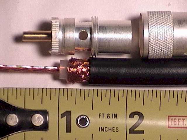
After the connector cools down, I again use the Ohm meter to check that the cable is not shorted. Here is a picture of the connector after soldering the center conductor, and the top two holes.
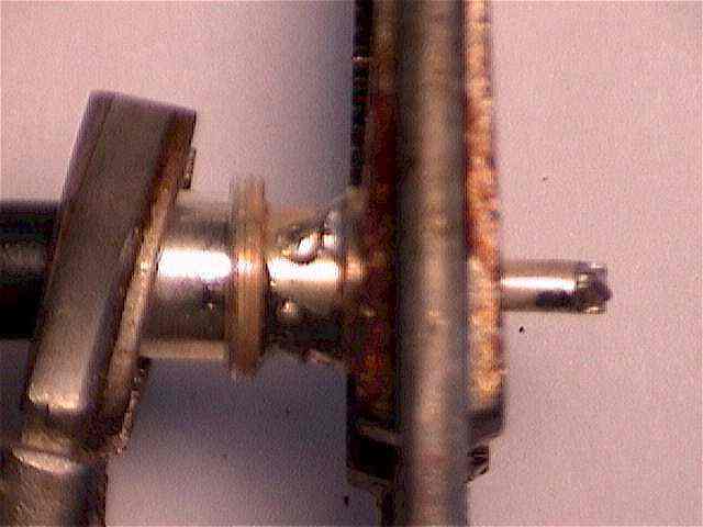 |
The holes have been completely filled with solder, providing protection against moisture getting into the end of the cable. When the cable is cool, I release the vise grips and rotate the cable 180 degrees so that the remaining two holes are pointing up. Those hole are soldered, and a final Ohm meter check guarantees that the cable is not shorted. Even with the vise grips acting as heat sinks, the connector will remain quite hot for several minutes. Please don't burn your fingers grabbing a hot plug. Some installation procedures suggest tinning the braid and/or center conductor before installation. I do not do that step. I find that I have no problems making strong solder joints, and tinning can cause big trouble if it adds enough solder so that the center conductor no longer fits into the barrel, or if the braid no longer fits within the PL-259 body. |
| Soldered Center Conductor and Top Two Holes |
I do not aim the torch directly at a hole, but between the holes. The only purpose of the holes (in my approach) is to provide a place to introduce the solder. If you are using sufficient heat, capillary action will suck the solder into the hole, and into the region between the holes. The goal is to have the braid soldered to the plug around the entire circumference of the coax. It is not just 4 dots of solder in the holes. Tinning the entire braid will improve the chances of accomplishing this. Whatever you do, aim for a soldered connection around the entire braid, not just dots at the holes.
In the November, 2001 issue of QST magazine, I noticed that Cable X-Perts installs a piece of heat-shrink tubing over the back end of their ready-made coaxial cable assemblies. This would provide additional protection against moisture infiltration through the back of the connector. While I have never seen the need for this added protection, it certainly can't hurt.
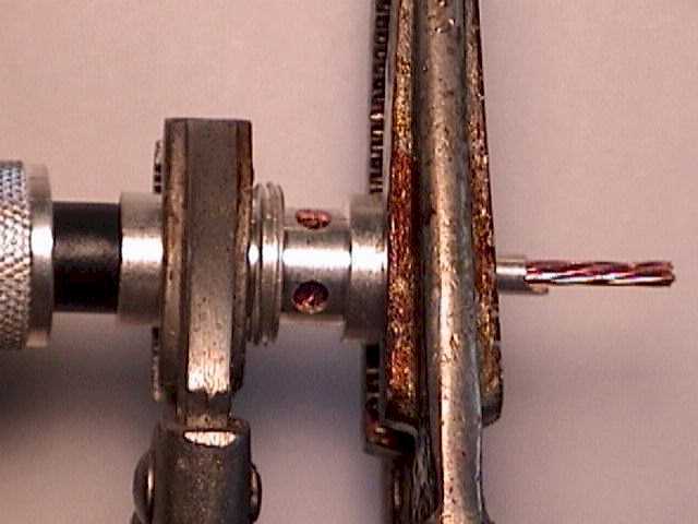
When using an adapter, the procedure is very similar. During the preparation phase, it is necessary to expose more braid. This braid is folded back on the adapter before the adapter is screwed into the PL-259.
 |
 |
 |
| Thin Coax with Adapter | Braid folded back on the Adapter | Adapter installed in PL-259 |
The left picture shows the adapter on the coax. The exposed braid has been extended to provide enough length so that when it is folded back onto the adapter, the braid covers the adapter all the way down to the threads. Do not let the braid slop over the threads, however, since it will be impossible to screw the adapter into the PL-259 if there is any braid on the threads.
The middle picture shows the braid folded back on the adapter. In addition, the center conductor has been stripped back, with a small amount of center insulator separating the braid from the center conductor.
The right picture shows the adapter installed in the PL-259, before soldering. The braid is visible through the holes in the PL-259 body. If you examine the end of the center pin barrel, you will notice that I've taken some folded over solid wire and inserted it into the barrel, next to the center conductor. In some cases, the center wire of the thinner coax is so much smaller than the center pin barrel that the only material connecting the two might be the solder itself. This is an undesirable condition, as solder is really meant to provide mechanical support, not an electrical connection. So, the hookup wire helps fill the large volume of the pin, and insures a positive metal to metal contact between the center conductor and the barrel. When the barrel is properly heated, the solder will flow into the barrel, and create a closed and mechanically rigid space.
At this point in the process the adapter installation merges with the normal installation, which is to say that you have to solder the center pin, then the two or four side holes, and then you are done.

About Us | Privacy Policy | Contact Us | ©2003-2009 Lee W. Besing, N5NTG - San Antonio Hams
